RANDOM PAGE
SITE SEARCH
LOG
IN
SIGN UP
HELP
To gain access to revision questions, please sign up and log in.
AS
A2
Bistable Latch / R S Flip Flop
One Bit Memory Circuit
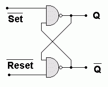
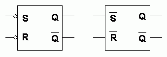
This circuit is commonly shown in three ways.
- Left: Two NAND Gates.
- Middle: Set and Reset are shown as little circles.
- Right: Set and Reset are labelled.


- RS stands for ReSet and Set. A zero is needed to set or reset. This is why there is overlining (opposite of underlining) to represent NOT.
- Q and Q are the outputs.
- If the Set pin is momentarily made zero, one or more times, Q will go high and stay high.
- If the Reset pin is momentarily made zero, one or more times, Q will go low and stay low.
- The first SET pulse changes the state of the BISTABLE. Subsequent SET pulses have no effect.
- The first RESET pulse changes the state of the BISTABLE. Subsequent RESET pulses have no effect.
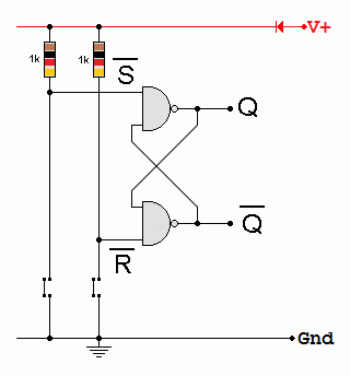
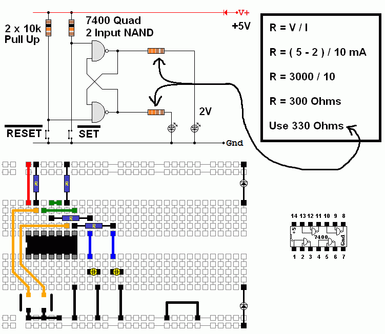
This circuit can also be used to debounce switches.
- The resistors are Pull Ups.
- The switches are Pull Downs.
- The NAND inputs are high due to the resistors until a switch is pressed. Then the input goes Low.


For the Falstad Circuit Simulation, CTRL+Click Bistable Latch
In options, check European Resistors and uncheck Conventional Current.
Click the switches to set and reset. Multiple clicks simulate switch bounce.
Alternatively view Bistable_Latch.txt.
Save or copy the text on the web page. Import the saved or copied text into the Falstad simulator.
Here is the new HTML5 Simulator Site.
reviseOmatic V3
Contacts, ©, Cookies, Data Protection and Disclaimers
Hosted at linode.com, London


